Introduction
Lifelike Products Inc make a number of HO-scale (1:87) models of the EMD GP38-2 (Geep Diesel Electric Road Switcher Locomotive). This article is my attempt to write about installing DCC on these locomotives – it isn’t a particularly simple task.
DISCLAIMER: This modification is hard. You can damage your new model VERY EASILY with the tools needed to perform the modification. These instructions are designed to make the process easier, and are based upon the successful modification of no less than eight Proto 2000 GP38-2 models.
However we can accept no liability for what happens to your model, nor do we guarantee that this modification will work. If you undertake the modification detailed here, you do so entirely at your own risk.
Remove it from it’s box – collect up the detail parts that have fallen off in shipping. Remove the two support brackets that hold it in place for shipping.

As ever with a DCC install, always check the loco runs correctly on DC before even starting the install.
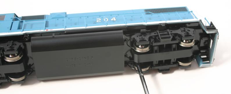
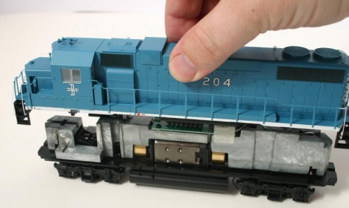
Remove the body – despite confusing instructions in the manual about them being secured by the brass screws when they’re all painted black (I don’t know about you but I’m really not that good at telling a black painted brass screw from a black painted steel screw by just it’s head. A masterly piece of useless documentation from the people at Lifelike.)
The screws you want are the ones hidden under the trucks (bogies) as illustrated here:
and here:

After that it should prove reasonably straightforward to just remove the shell of the loco.
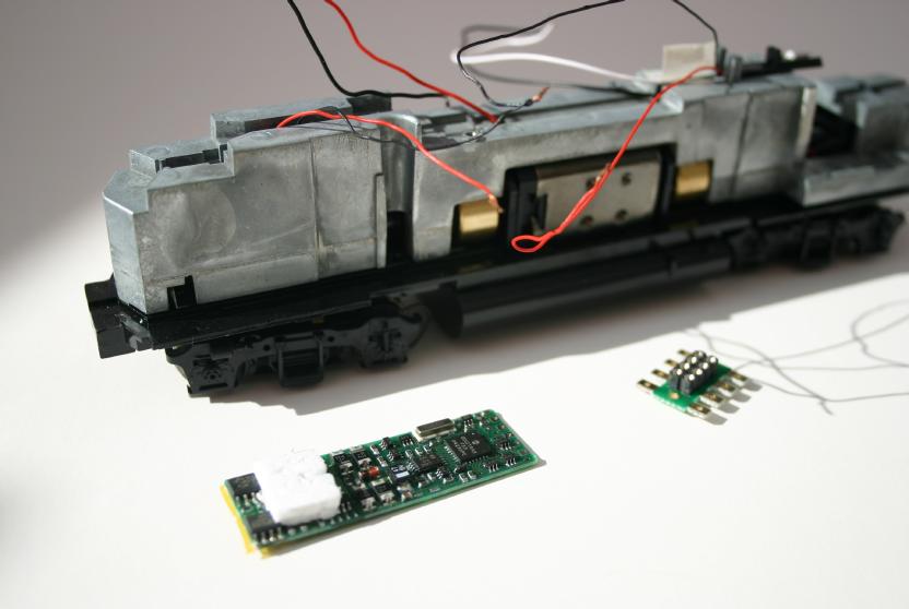
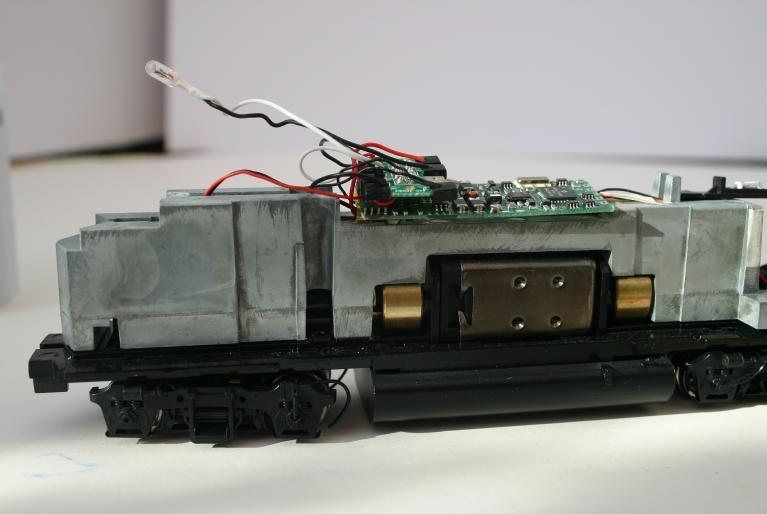
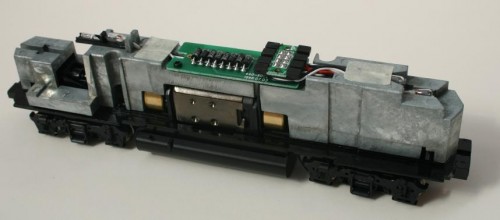
You’ll be left with the Chassis looking like this. The tidy look and apparently open connector belies just how much work lies ahead to get this thing to actually work right with DCC.
Removing The Wires
After bad experiences with a melted roof, I’d say you have two choices at this point – replace all four bulbs with LEDs, or use a DCC decoder with a low current/low voltage output such as the Digitrax DH165L0 (or the previous non-RoHS DH163L0 if you find one on a dealers shelf) or TCS A6X decoders.
After my bad experiences with a Lenz LE1035 (due to the appalling vagueness of the Proto 2000 manual leading me to fitting the wrong type of replacement bulbs), I found the DH163L0 decoder intended specifically for this breed of Proto 2000 unit. Unfortunately this only caters for the headlights using the factory fitted bulbs; works fine on the Proto 2000 USRA 0-8-0 and probably GP30 etc, the four bulbs of the GP38-2 model present a problem.
The headlights are catered for, but the two number board lights are not; I replace them with LEDs since the bluer colour is much less of a problem when shone through the numberboards.
Since I did the first batch with DH163L0s, I’ve continued with this chip, although the more recently released TCS A6X with it’s six balanced low voltage outputs would save any need to replace bulbs (but would be a little bigger (awkward) and would require a completely socketless install).
If you pull off the push-on plastic caps, unscrew the main PCB from the chassis, you’ll be left with it looking like this – the Digitrax DH163L0 board is visible in front. At the right hand end of the Digitrax DH163L0 decoder, you should be able to see five little holes in the DCC PCB. These are the solder points for the additional functions. I’m pretty certain (please check) that the centre one is the blue/+Common (function common) and one of the points just next to it is the F1 output.
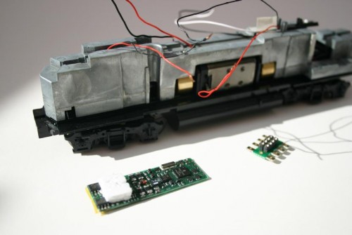
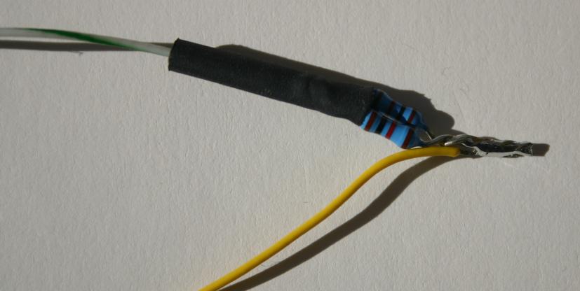
I then build a small wiring loom which consists of a wire that will run in the channel under the PCB towards the front of the loco. There is a reasonable cavity just under where the cab will be where the resistors for the number board LEDs can be placed. I therefore bring the function common forward to this location where I place a little package of two 1K 1/6th watt resistors wired in parallel.
This gives 500 ohms which is about right (I’m told) and using two smaller resistors in parallel creates more surface area to disapate the heat generated. (Least that’s my theory; remember, melted roof first time, I’m nervous about where the heat goes!). One leg of the front number board LED is soldered to the end of the resistor pack (but only after testing the basic install because I’m no good at telling which pin is which on an LED – I prefer to offer it up and see it shine before soldering it in!).
A return wire back under the DCC PCB takes the low current feed back to the rear of the locomotive for the rear number board LED.
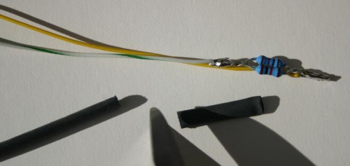
The resistor package itself is then sealed in heat shrink. Once done it
looks like this:

At this point in the install, the light started failing me and I completed the install on B&M #204 by artificial light and couldn’t take any more photos worth sharing. I now have three more units to do and will photograph the next stages of the process as I do those.

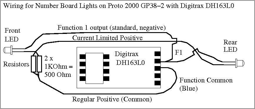
Here is a diagramme that tries to explain how the extra components are added to make the LEDs work. Note that the best place for the resistor package to fit is in a gap in the chassis in front of the DCC board near the cab (under the dynamic brake blister on the model). The extra wiring loom carrying it left of the board is to indicate approximate lengths of the needed cables, layout, etc.

Quick Summary: Basically you re-wire the 8-pin connector such that the normal pins are connected – pickups to power in, motor to the two motor pins – F0-Front to the front headlight, F0-Rear to the rear headlight. Do the usual safety tests on the programming track, set the address and check it runs.
Then offer up the LED, find which way round it glows and solder it to the resistor package or the lead from it. Repeat for the other LED. Check on a programming track again to make sure there’s no new short circuit, and then
reassemble the loco. Note that the position of the light pipes is such that one LED is on top, while the other is below the bulb.


 Tools for adjusting the gauge of the wheels:
 A friend of mine pointed me to these